Leaderboard
-
[[Template core/front/popular/memberRow is throwing an error. This theme may be out of date. Run the support tool in the AdminCP to restore the default theme.]]
[[Template core/front/popular/memberRow is throwing an error. This theme may be out of date. Run the support tool in the AdminCP to restore the default theme.]]
[[Template core/front/popular/memberRow is throwing an error. This theme may be out of date. Run the support tool in the AdminCP to restore the default theme.]]
[[Template core/front/popular/memberRow is throwing an error. This theme may be out of date. Run the support tool in the AdminCP to restore the default theme.]]
Popular Content
Showing content with the highest reputation since 06/14/26 in all areas
-
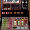
So the real VFD came in to the workshop as dead, and it was. These devices are quite pricey and I did warn the owner it might not be repairable. However trusty soldering iron in one hand and meter in the other I dived in casting caution to the wind. It has 3 electrolytic caps, 2 x SMD and one through hole. Both SMD caps were effectively open circuit but all three were changed to 105° types. Once these were done and the device powered up the screen was still blank so I needed to drive it with something. Looking up the spec sheet it showed that the SIN/TO pin, if grounded, would switch to test mode and by jove it did, displaying the whole character set. Sending it back for testing expecting a glowing report proved a bit premature. The device was still dead and the machine would only boot up without the VFD connected?? When it arrived again at the workshop I swear it was poking it's tongue out at me. Anyway not to be outdone it was time for a bit more researching. Next to no info on the web, no diagrams or fault repairs on Youtube. So first step was to find out why it was stopping the board from booting. This VFD connects to the 14 way DIL connector via the little PSU board. The only wire which goes directly from the VFD to the board is the BUSY link. I assume this is used to slow the main board logic when it needs to print lots of text to the screen. When this connection was removed everything burst into life! Checking with a meter showed it to be permanently HIGH. Here's a pic of the board so you can see what I was dealing with... Did the BUSY line go direct to one of the LSI chips because if it did that was goodnight Vienna! Trying to trace tracks on this was no easy task either but the BUSY line did appear on the O/P of IC2. This was a single OR gate and the output was stuck high. Checking the I/P showed a nice waveform but nothing on the O/P. I managed to find some replacements on Ebay at a reasonable price and slipped in a new one and bingo, nice waveform on the O/P and with the BUSY link re-connected everything burst into life. You have to take precautions when reworking these boards due to the proximity of other components and plastic parts. Best thing for this is Kapton tape to shield the bits you don't want melted.3 points
-
Ah glad you got sorted1 point
-
Thankyou so much for looking , Nick as found one for me :)) appreciate your help tho 👍1 point
-
Sorry Phil, only got a green start collect button1 point
-
i had a address issue once , someone got my postcode and house number wrong1 point