Leaderboard
-
[[Template core/front/popular/memberRow is throwing an error. This theme may be out of date. Run the support tool in the AdminCP to restore the default theme.]]
[[Template core/front/popular/memberRow is throwing an error. This theme may be out of date. Run the support tool in the AdminCP to restore the default theme.]]
[[Template core/front/popular/memberRow is throwing an error. This theme may be out of date. Run the support tool in the AdminCP to restore the default theme.]]
[[Template core/front/popular/memberRow is throwing an error. This theme may be out of date. Run the support tool in the AdminCP to restore the default theme.]]
Popular Content
Showing content with the highest reputation on 02/05/19 in Posts
-
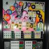
So,this has a hantarex monitor as in pic.Im rebuilding the 5 volt supply,it seems the power supply gives about 15 to 20v dc to the board,which is then regulated to 5v via the regulator and 2 big caps as in pic.So these 3 parts are being replaced.As the machine has been stood for at least 20 years is there anything i should replace on the monitor board.The voltage reg is 5volt 3 amp.1 point
-
Being as it's a bit quiet here.................... Well I've had quite a productive day in the workshop trying to work out some code to make the tester easier to use. I've dug out my trusty Arduino yet again and managed to cobble together some code along with a bit of borrowing off of other folks from the web. So far I've managed to get all the lamps tested so that they all switch on and off one at a time so that takes care of the outputs. Next step is to try and get the switch sensing to bring up an associated lamp (LED) per switch so I can check all the inputs. Once that's completed I'm thinking at having a go at spinning the reels. I know a few folks have hit snags with this but just for the fun of it I'm going to give it a go. The good thing about this is it really makes you understand how it all works. I thought I understood it all before, but now I know I do. When I get a bit further I'll post a vid and the details so if anyone else wants to use it, or better improve on it, they can.1 point
-
nice one matty and thanks for the board mate1 point
-
Thanks for the replies. I have made a change machine. Made a LED driver board with a couple of 8 bit shift registers. Just got me thinking how nice it would be to make a PCB. I will show you all my progress once my parts arrive and can actually make it up. I'll also check out diptrace. Where do you get the actual boards made Andrew?1 point
-
Might as well check it's present, I don't know if it would operate without it.1 point
-
The 100Hz might be used for timing on the board or possibly for a zero crossing detector to operate the hopper and solenoids?1 point
-
Swansea duo of SRU goodness in 2019😁1 point
-
thanks mate once you put solder over the top it it dont look that bad and solder mask paint its better than them wires you can see next to it1 point
-
hi guys thought i would do a little track repairs ran out of wire so than found these ribbon tags of tvs so i peeled the little copper traces of them stuck them on the board reflow with solder over them tracks now fixed hope this helps some one1 point
-
thanks mark fit once check plugs twice happy days1 point
-
yes mate doing your board with them its easier and fits snug to the board and its better than having wires all over the board1 point
-
You are popping up all over the place See advice in your own thread1 point
-
And i have done so too in the past, but then come the posts about making coin from poor collectors etc, when all I have done is come up with things to help with the problems encountered, but that’s life I guess!!! I learnt !!1 point
-
theses are the tvs tags1 point
-
😂 brilliant!1 point
-
looking at yours and mine avatars, i can tell were going to get along just fine! lol.1 point
-
I seem to remember 0.02mA being good before mods, but I don't bother measuring before mods any more because the strnsistors / R25 thing just seem to fail one after the other on the forst MPU I sussed the battery current on, now I just replace to avoid future problems. The standard battery is 80mAh at 3.6V, so you can work out a theoretical maximum backup bu deviding the current by the mAh... 80/0.02 = 4000 hours, 166 days Wow at my target curent of 0.001mA it looks like there is no theoretical point charging the battery as it would probabley leak before it drained 80,000 hours / 3333 days (10 years), But that's assuming zero leakage and the battery holds the full mAh and can hold that current at full voltage... but it's not reality.1 point